")
")
This example demonstrates the use of an M5S digital input module (M5S-BID0524B1) to detect a voltage of 24 V DC. It reads a digital input using the digitalRead function and prints the result to the Serial Monitor.
Since the code uses pinMode(INPUT_PULLUP) instead of pinMode(INPUT), no external pull-up resistor is required. An internal resistor of 20 kΩ in Arduino pulls the input pin to 5 V in passive state. This configuration causes the input to read HIGH when the input module is OFF, and LOW when it is ON.
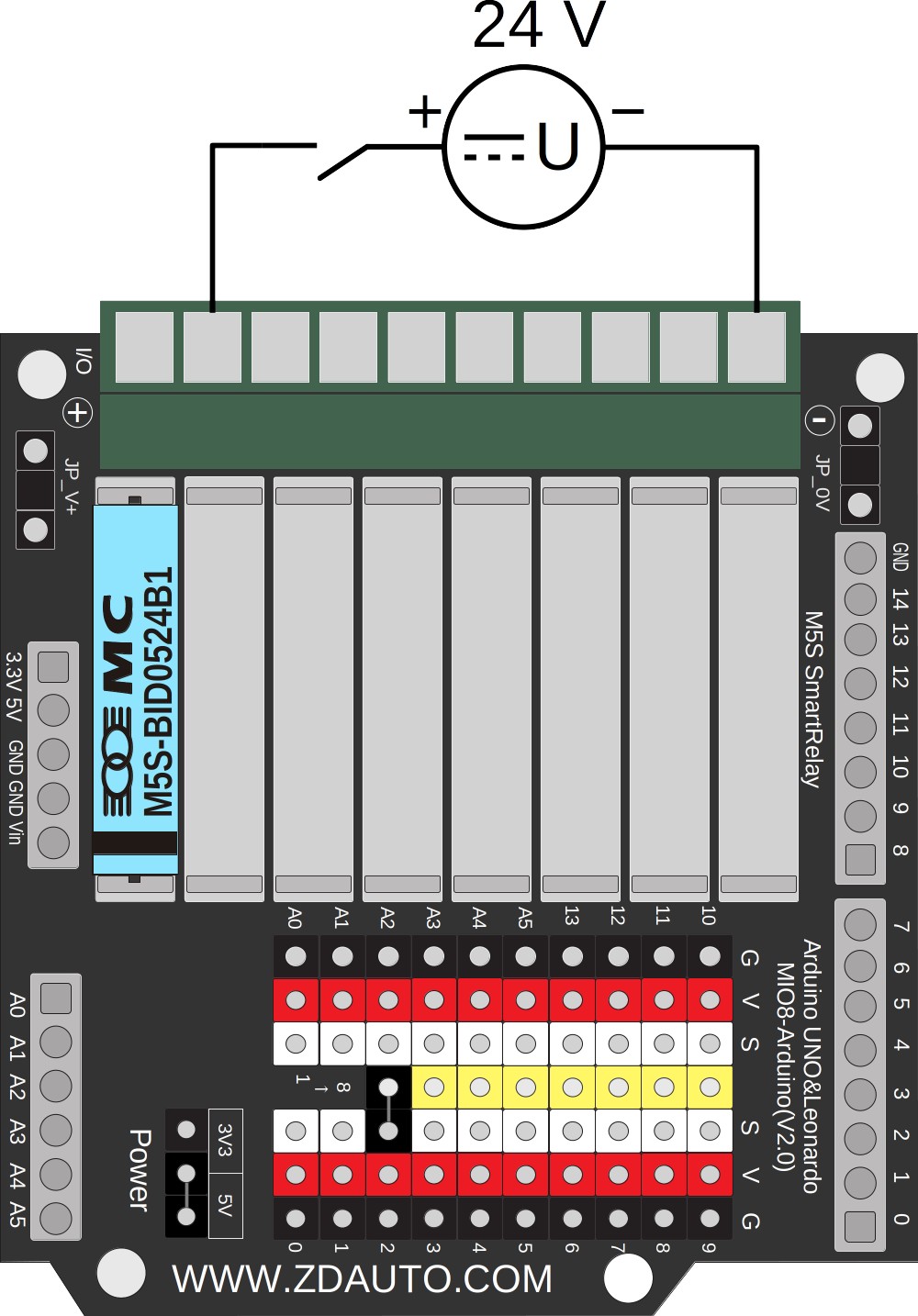
The circuit
- External: M5S digital input module detecting a voltage of 24 V DC.
- Internal: M5S digital input module connected to Arduino digital pin 2.
Characteristics of different input modules
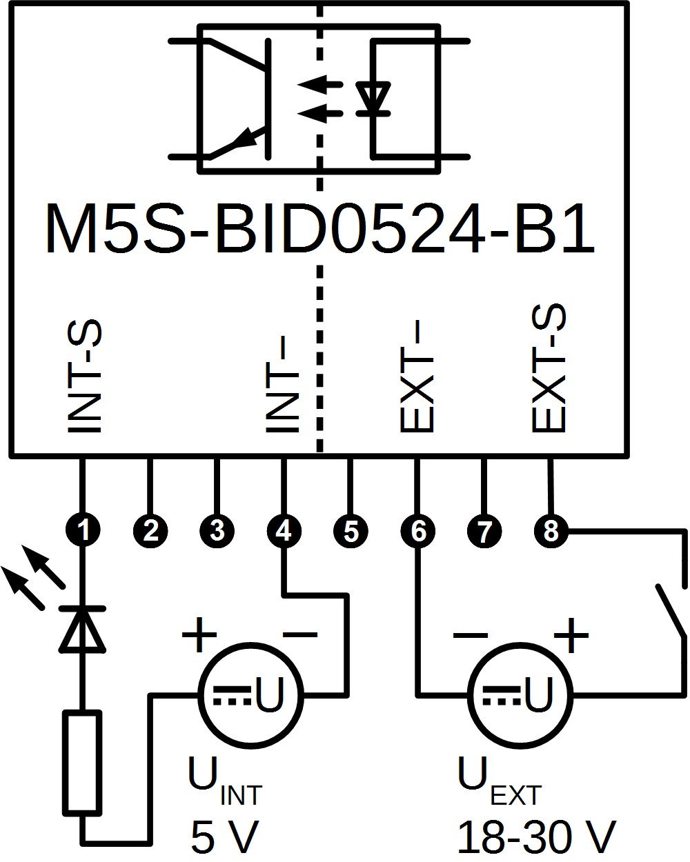
- M5S-BID0524B1
M5S input Uext    -> M5S ON  -> Arduino pin voltage 0 V -> Arduino value 0 (LOW)
M5S input passive -> M5S OFF -> Arduino pin voltage 5 V -> Arduino value 1 (HIGH) - M5S-BID0524A1
M5S input GND     -> M5S ON  -> Arduino pin voltage 0 V -> Arduino value 0 (LOW)
M5S input passive -> M5S OFF -> Arduino pin voltage 5 V -> Arduino value 1 (HIGH)
Code
void setup() {
  Serial.begin(9600);       // start serial connection
  pinMode(2, INPUT_PULLUP); // configure pin 2 as an input and enable the internal pull-up resistor
}

void loop() {
  int sensorVal = digitalRead(2); // read the value of pin 2 into a variable
  Serial.println(sensorVal);      // print the value to the Serial Monitor
}
This example code is based on the Arduino default example:
http://www.arduino.cc/en/Tutorial/InputPullupSerial